
In this post, a special purpose circuit, namely Silo Emulator is briefly presented.
Overview
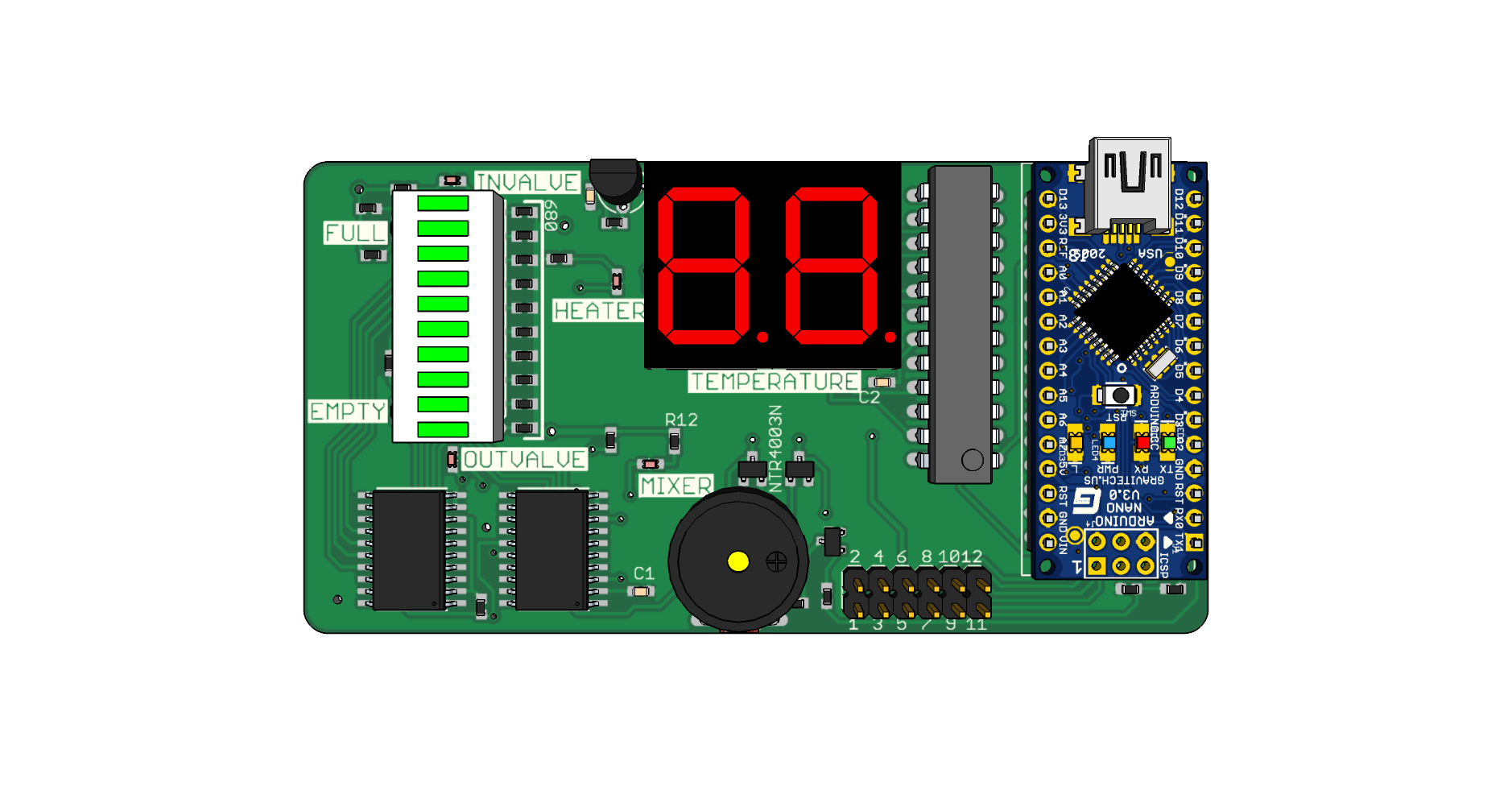
Silo emulator is an arduino-based board implementing the full (incl. mixer and heater) silo interface as described in the liqueur plant case study. It was developed with the intention of testing the control system for an industrial plant, developed as part of my thesis, but at a later time it was used as a lab equipment for “Advanced Programming Techniques” class of Electrical & Computer Engineering department, University of Patras.
Briefly, it emulates a physical industrial liquid silo equipped with sensors (full, empty, thermometer) and actuators (heater, mixer, input valve, output valve).
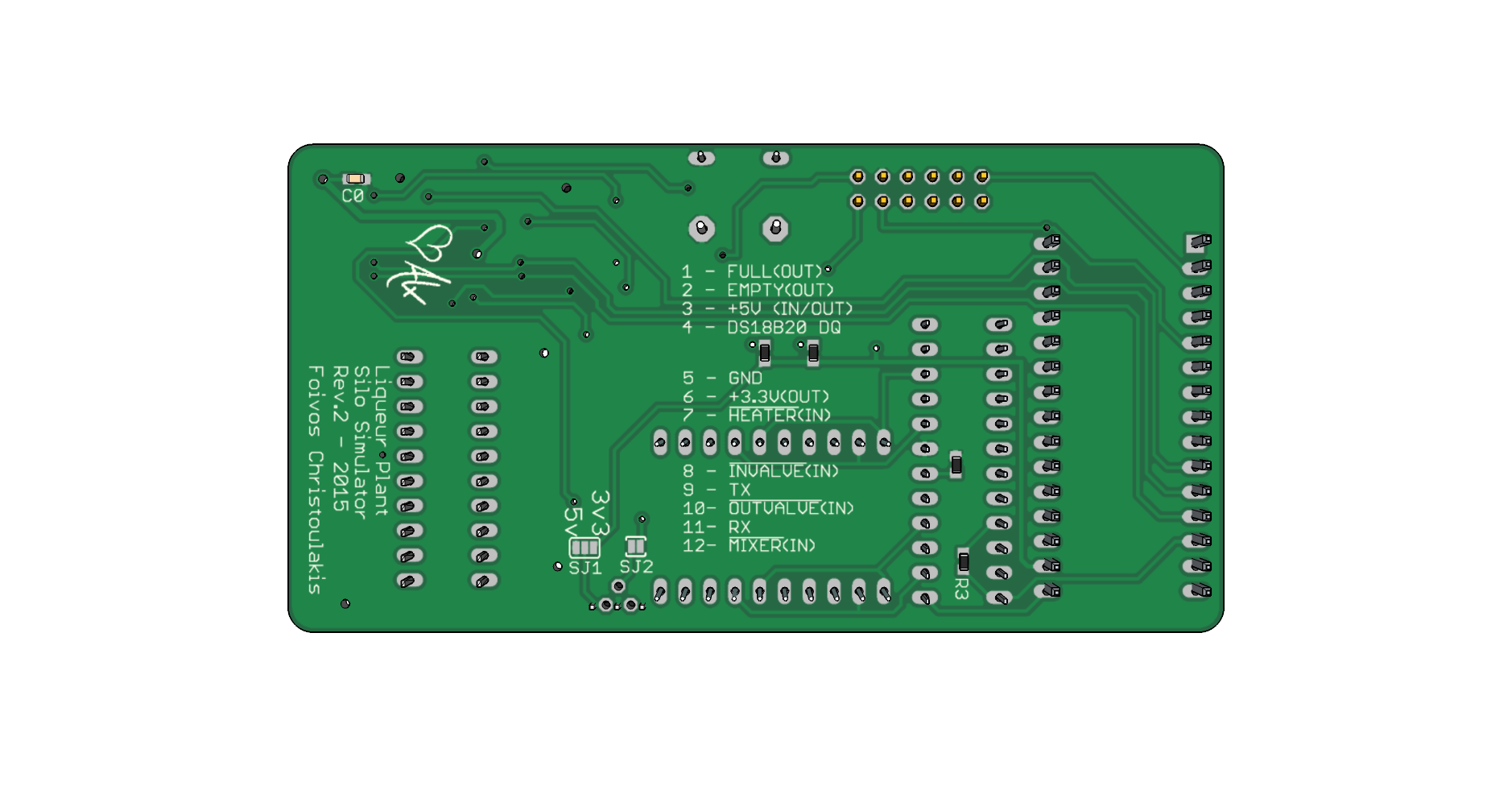
Silo Emulator’s complete documentation is available here
Circuit implementation details
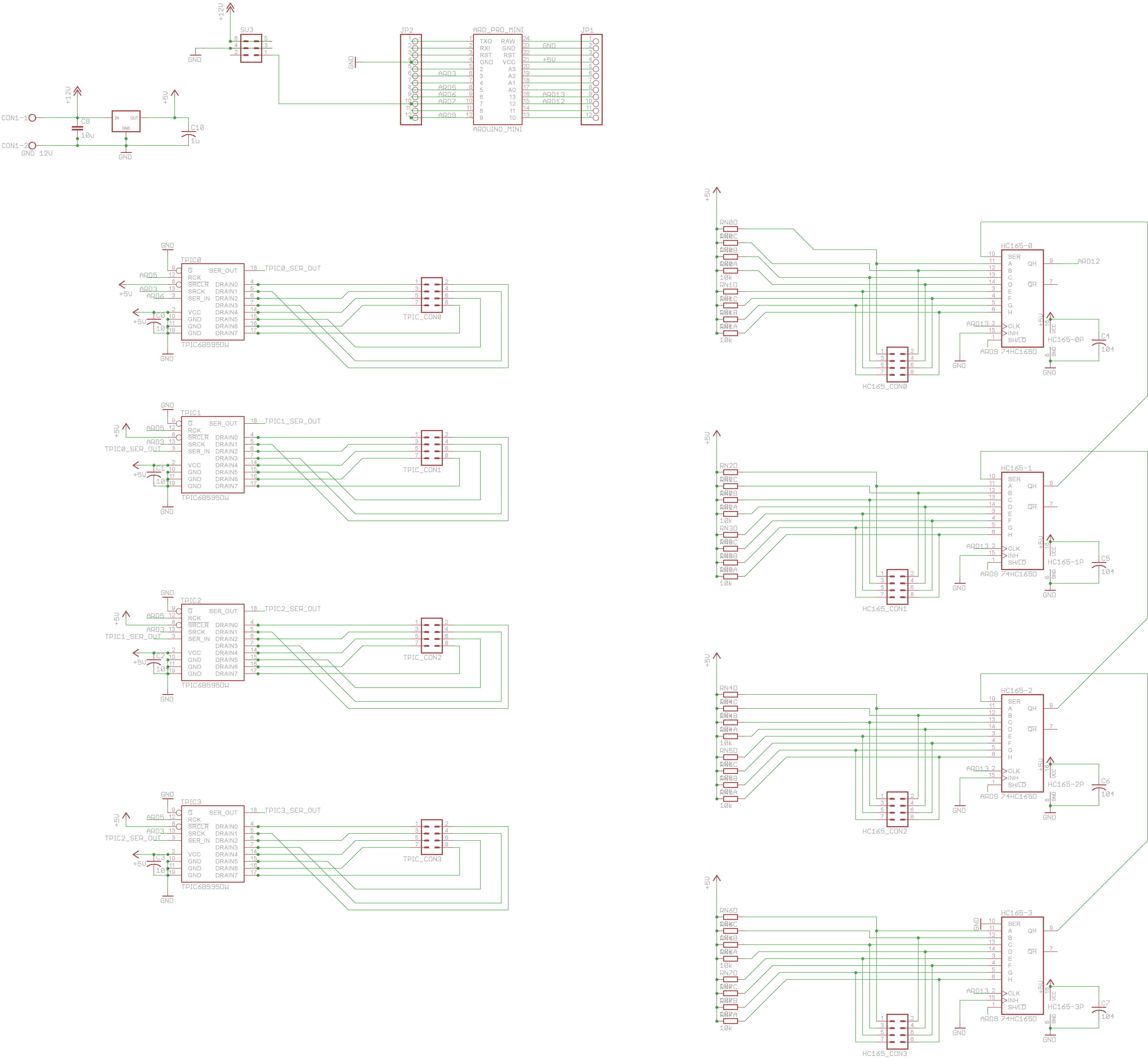
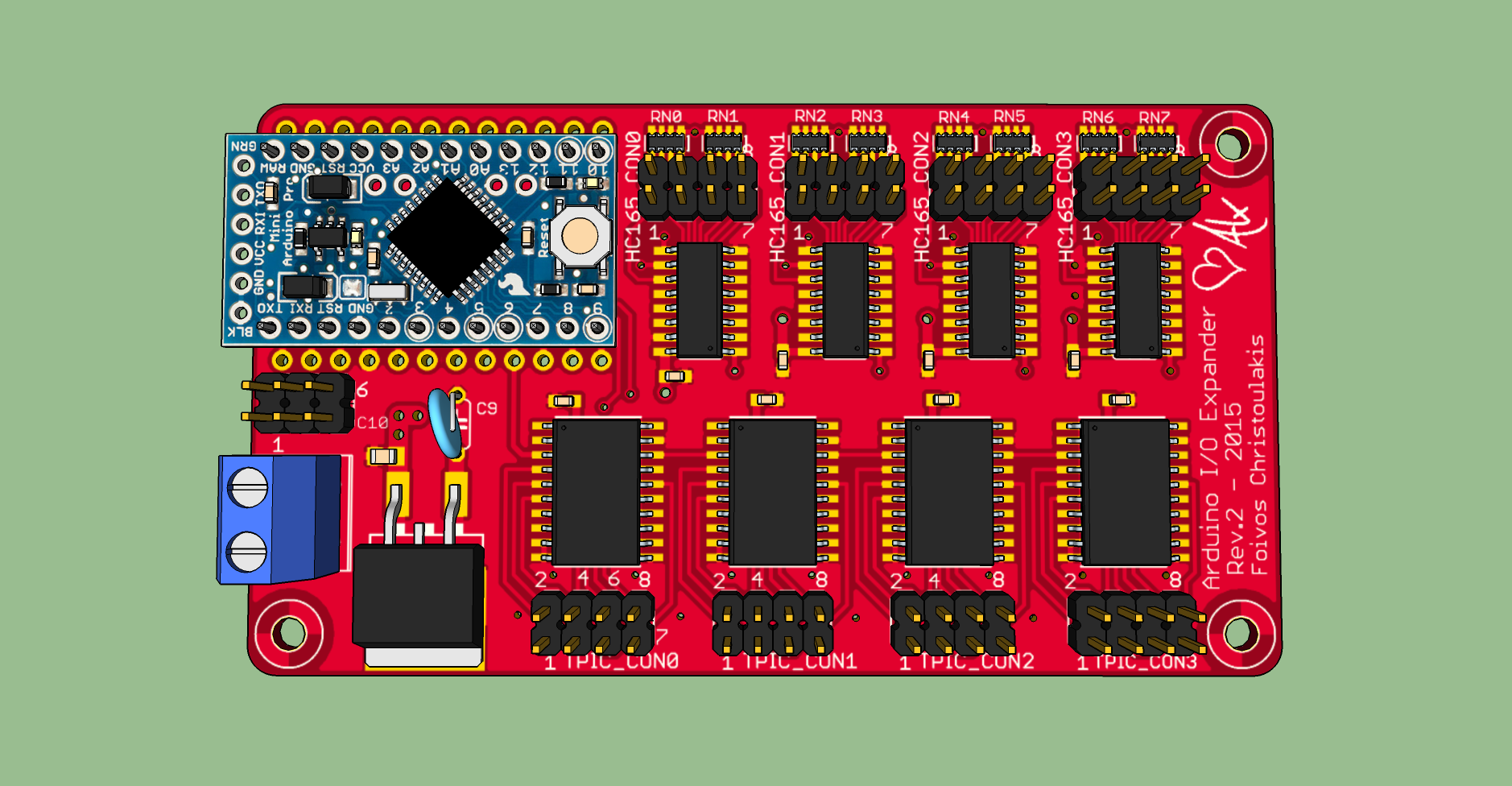
I won’t go into too much detail but in order to drive all the necessary LEDs, a power shift register (serial-in parallel-out register integrated with one open-drain DMOS transistor on each of the outputs) was utilized. Conveniently, the total number of the LEDs on the board (apart from the 7-segment display) is exactly 16, hence two 8-bit shift registers were adequate. As for driving the temperature indication (two 7-segment numeric displays) the solution of a LED display driver IC (MAX7219) was adopted.
The circuit was designed to interface directly with 3.3V controllers and arduino nano logic level is at 5V, therefore some level shifting was required. The inputs of the board could be connected directly to the input-declared I/O pins of the arduino nano. That’s because AVR328p’s datasheet states that for Vcc=5V, Vih=3V, which means that a 3.3V signal will register as logic high. The TX signal of the serial connection was shifted to 3.3V with a voltage divider (2KΩ,1KΩ resistors) and the output binary signals were level-shifted with resistive-load single-NMOS inverters. Different technique was used on the latter considering these outputs ought to be active-low.
Software architecture
The firmware was designed in an object oriented fashion and is based on three main classes.
InputsHandler: This singleton class constantly reads the inputs of the circuit, encode their current values in a byte and passes this byte toLogicImplementerby invokingLogicImplementer.setCurrentInputs()method.LogicImplementer: This (also singleton) class implements the core logic of the emulation. It internally uses two timers for the necessary (for liquid level and temperatures time-dependent changes) time keeping. When a timer event denotes a change of the temperature it invokes methodsetTemperature()of classOutputsHandler. At the same time, whenever the methodLogicImplementer.setCurrentInputs()is invoked, it calculates (according to the current inputs’ state) the current state of the silo and subsequently the value of all the binary outputs of the circuit. If any output’s value has changed and should be updated, it invokesOutputsHandler.setOutputs()method and passes toOutputsHandlerthe output’s values encoded in a 16-bit word.OutputsHandler: This class encapsulates the implementation-specific manner of transferring information from the microcontroller to the rest of circuit (SPI interface).
Demonstration
You can see a typical usage scenario of the circuit in the following video: